


 Forklift LiFePo4 Battery
 Golf Cart LiFePo4 Battery
 Battery Charger
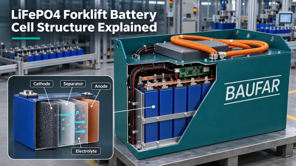
Table of Contents
LiFePO4 forklift battery cell structure matters because a traction battery must deliver both energy and short bursts of power while operating through vibration, temperature changes and repeated charging. A buyer does not need to become an electrochemist, but understanding what happens inside the cell makes it easier to evaluate C-rate, charging limits, thermal control, BMS settings and realistic cycle-life claims.
At BAUFAR, we treat the cell as the starting point rather than the finished product. A well-selected cell can still underperform if the pack has weak electrical connections, poor temperature control, incorrect charging logic or inconsistent cell matching. The useful engineering question is therefore not only “What is inside a cell?” but also “How is cell behavior managed inside the complete forklift battery?”
What Is Inside a LiFePO4 Forklift Battery Cell?
A rechargeable lithium-ion cell contains several tightly integrated layers and components. In a typical prismatic LiFePO4 cell used for industrial applications, the main elements are:
- Cathode: lithium iron phosphate, or LiFePO4, coated on an aluminum current collector.
- Anode: commonly graphite coated on a copper current collector.
- Separator: a thin microporous polymer membrane that physically separates the electrodes while allowing lithium ions to pass.
- Electrolyte: an ion-conducting medium, typically based on lithium salt in organic solvents in conventional liquid-electrolyte cells.
- Current collectors and terminals: conductive paths that connect the electrode layers to the external circuit.
- Cell case and safety features: a sealed enclosure with terminals and design-specific venting or pressure-relief provisions.
Manufacturers make the cathode, separator and anode as thin layers, then wind or stack them into the cell. That construction creates a large active surface area inside a compact cell. The exact materials, coating thickness, porosity, electrolyte quantity and manufacturing quality all influence resistance, capacity, power capability and aging.
Why LiFePO4 is a chemistry, not a complete specification
LiFePO4 identifies the cathode chemistry. It does not tell the buyer the cell’s usable capacity, internal resistance, allowed charge rate, low-temperature limit or quality consistency. Two cells described as LFP can perform differently because of electrode design, particle structure, electrolyte system, manufacturing control and test criteria.
Buyers comparing specifications can use BAUFAR’s guide on how to choose a LiFePO4 battery as a starting point, then request application-specific data for the target forklift.
How Lithium Ions and Electrons Move
During charging
The charger applies electrical energy to the cell. Lithium ions move from the LiFePO4 cathode through the electrolyte and separator toward the graphite anode. Electrons cannot travel through the separator; they move through the external charging circuit to the anode side. The ion and electron paths are separate but coordinated.
During discharge
When the forklift draws power, the process reverses. Lithium ions move from the graphite anode through the electrolyte toward the cathode, while electrons travel through the external circuit to the inverter, motor and hydraulic system before returning to the positive side of the battery.
Energy capacity and power measure different characteristics. Capacity describes how much charge the cell can store. Power depends on how quickly the cell can deliver energy without exceeding voltage, current and temperature limits. BAUFAR’s explanation of Ah, Wh, C-rate, SOC and SOH helps connect these cell-level processes to a complete forklift battery specification.
LiFePO4 Forklift Battery Cell Structure and SEI Aging
During the first cycles, electrolyte reactions at the graphite anode form a passivation layer called the solid electrolyte interphase, or SEI. A stable SEI supports lithium-ion transport while limiting continued electrolyte decomposition. Its formation consumes some cyclable lithium, and continued growth over time can increase resistance and reduce available capacity.
Several mechanisms drive battery aging. They include loss of cyclable lithium, growth of interfacial layers, changes in electrode structure, electrolyte decomposition, corrosion and mechanical damage. Temperature, SOC range, charge and discharge current, time and cell design determine which mechanism dominates.
Why low-temperature fast charging needs control
If charging current is too high for the cell temperature and SOC, lithium can deposit on the anode surface instead of entering the graphite structure. This lithium plating can reduce capacity and create safety concerns. A suitable BMS therefore restricts or blocks charging when measured conditions fall outside the validated limits. In cold environments, the system may need to heat the cells before charging.
Why high temperature also accelerates aging
Higher temperature can reduce impedance in the short term, but it also accelerates unwanted chemical reactions. Pack design must prevent local hot spots and large temperature differences between cells. It is not enough to quote one ambient operating range; buyers should request cell-temperature limits, derating logic and test conditions.
From One Cell to a Forklift Battery Pack
A forklift needs far more voltage and energy than one prismatic cell can provide. Pack designers connect cells in series to increase voltage and, where necessary, in parallel to increase capacity and current capability. The complete pack adds mechanical, electrical and control systems around the cells.
Cell matching and mechanical restraint
Cells in one series string carry the same current. A cell with lower capacity or higher resistance can reach its voltage or temperature limit first, causing the BMS to reduce power or stop charging. Pack assembly should therefore control cell batch, capacity, resistance and state-of-charge consistency.
Prismatic cells also need appropriate support and restraint according to the cell manufacturer’s requirements. Engineers must account for vibration, shock, terminal stress and expansion. Excessive movement can damage connections, while incorrect compression can create other mechanical problems.
Busbars, cables and contact resistance
Engineers must size and assemble high-current connections for the expected continuous and peak load. A loose or contaminated connection creates resistance and heat even when the cells themselves remain within limits. Torque control, surface preparation, insulation and routing are therefore part of battery performance, not secondary assembly details.
BMS, contactors and protection
The battery management system measures cell voltage, pack current and temperature, estimates SOC and SOH, controls contactors and communicates with the charger and truck. The BMS does not improve weak cells by software; it keeps the pack within validated boundaries and identifies developing imbalance or faults.
Readers who want a deeper explanation can review what a forklift battery BMS does. The complete system may also include fuses, precharge circuits, service disconnects, current sensors, insulation monitoring and emergency shutdown functions, depending on voltage and application.
Why Forklift Duty Requires More Than Consumer Battery Design
A forklift battery repeatedly supplies traction and hydraulic loads. Acceleration, lifting and steering can create short high-current events, while multi-shift fleets may use opportunity charging between tasks. The pack also experiences vibration, impact, dust, moisture and temperature variation. These conditions make cell selection and system integration inseparable.
For example, a cell may have enough nominal energy for a shift but still be unsuitable if its peak current limit cannot support lift demand at low SOC. A charger may deliver the desired current, but the BMS must reduce charging current when cells are cold or hot. A battery may fit the compartment, but its mass, restraint and cable routing must still meet the truck’s mechanical requirements.
BAUFAR’s forklift lithium battery components guide shows how cells, plugs, displays, chargers and installation details form one operating system.
What Buyers Should Ask About the Cells
Electrical and thermal data
- Nominal capacity and the conditions used to measure it.
- DC internal resistance and the measurement method.
- Continuous and pulse current limits with duration.
- Permitted charge and discharge temperature ranges.
- Voltage limits and recommended SOC window.
- Heat generation or temperature-rise data at relevant C-rates.
Life and validation data
- Cycle-life test temperature, C-rate and depth of discharge.
- End-of-life capacity criterion used in the test.
- Calendar-aging conditions and storage recommendations.
- Cell-level safety and transport test documentation.
- Lot traceability and incoming inspection records.
Pack integration data
- Cell matching criteria and balancing strategy.
- Mechanical restraint and vibration validation.
- Temperature-sensor locations and thermal uniformity.
- BMS limits, fault responses and CAN communication.
- Busbar, fuse, contactor and connector ratings.
- Service access and module or pack replacement strategy.
What Makes a Good Forklift Battery?
Buyers should not judge a forklift battery by cathode chemistry or a cycle number alone. The cells must match the real energy and power demand. The mechanical structure must protect them. Electrical connections must remain low-resistance. The thermal design must keep cells within their validated range, and the BMS must coordinate the battery with both charger and truck.
From BAUFAR’s perspective, the best specification states its conditions clearly. Reliable cycle-life data includes temperature, charge rate, discharge rate, depth of discharge and end-of-life criterion. Fast-charge claims should define the allowed SOC and temperature window. A credible pack design explains how the BMS monitors and controls cell behavior in the actual forklift.
Understanding LiFePO4 forklift battery cell structure is therefore useful because it connects chemistry to purchasing decisions. The cathode, anode, separator and electrolyte make reversible energy storage possible; the pack engineering determines whether that chemistry can work reliably in daily industrial service.
Featured Forklift LiFePo4 Battery
48V Forklift Battery
51.2v 460Ah Forklift Lithium Battery For BT RR-M6
48V Forklift Battery
Nichiyu FB25PN-75 Forklift Lifepo4 Battery 48V 460Ah
80V Forklift Battery
Forklift Lithium-ion Battery 80v 404Ah for Toyota 7FB30-7FBJ35
48V Forklift Battery
Forklift Lithium Battery 51.2v 404Ah for Still FM-X
48V Forklift Battery
48V 519Ah Lifepo4 Lithium Battery for Heli CPD20/25-GB2/GD Forklift
80V Forklift Battery
80V 404Ah Lifepo4 Lithium Battery for CPD30/35-G1/G3 Forklift
80V Forklift Battery
80V 560AH Lifepo4 Lithium Battery for HELI CPD35-GD2
80V Forklift Battery
80V 600Ah LiFePO4 Lithium Battery for NICHIYU FBC25/30P Forklift